Last year, Automation World examined the differences between accuracy, resolution, and precision in the encoder world. And while understanding the differences among these terms is important to understanding encoder function, it’s even more important to effectively determine the correct type of encoder for your application.
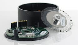
The core function of an encoder is to provide feedback to a controller on the position of moving parts in a machine or electromechanical system. “Encoders close the feedback loop and tell you exactly what a moving part in your system is doing,” said Neal Donowitz, COO, US Digital, a supplier of encoders.
Given the feedback role of encoders in a motion control system, Donowitz said the first decision in your encoder selection process should be based on the type of motion in your application.
“Linear motion occurs in a straight line—back and forth. Therefore, linear encoders are made to be used in applications like reporting the position of a forcer in a linear motor, or distance in digital calipers,” he said.
Rotary encoders are typically attached to a motor to report motor shaft position. Donowitz added that they can also be used “with anything that rotates. For example, they can report the angle of flaps on an airplane, or the angle of a robot’s arm.”
The information from either type of encoder—linear or rotary—is used by a motion controller to calculate position, speed, distance, and direction.
Optical, Magnetic or Capacitive
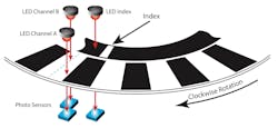
Once the type of motion to be monitored in your system has been determined, the next step is determining which of the three types of encoders are best for the application—optical, magnetic or capacitive.
Because optical encoders function best when nothing gets in the way of the light path, operation environments with high humidity, moisture or excessive dust can cause problems for optical encoders unless addressed by specialty packaging.
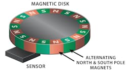
Magnetic encoders typically have a magnet attached to a rotating shaft so that a stationary sensor can detect the north-south field lines from the magnet and report the angle of the magnetic field as the shaft rotates.
Capacitive encoders are the newest type of encoder technology. These encoders detect changes in capacitance and relate that change to position. “Inside the encoder, a transmitter sends a high frequency signal past a rotor to a receiver,” said Donowitz. “The rotor modulates the signal and the receiver translates the modulated signal, which is then sent to the motion controller.”
He explained that capacitive encoders draw less current than optical and magnetic encoders and perform well in environments with dust, moisture or condensation. However, the maximum speeds of capacitive encoders are “often less than optical encoders,” he noted.
Incremental, Absolute or Pseudo-Absolute
Understanding how encoders capture position data is one important decision factor. The other is in how encoders report the position information they collect.
According to Donowitz, there are two primary ways encoders report this information, with a third method being a hybrid approach to the two primary methods.
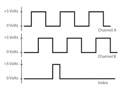
Incremental encoders report relative position, he said. “As the internal disk rotates or a linear strip moves, the encoder will transmit a high or low pulse for each increment of motion. Two output channels, often called Channel A and Channel B, are typically used to send signals to a motion controller. The channels are offset from each other by 90 electrical degrees—a phase difference known as quadrature—which allows the motion controller to determine direction of motion.”
Because the pulses transmitted by incremental encoders are simple to process, Donowitz said these encoders are recognized as being good choices for position and speed control. They are particularly effective at high speeds because they continuously stream output pulses. The main drawback for this type of encoder is that they will lose position information if power is lost or cycled.
As their name implies, absolute encoders report absolute position—even if power is cycled. “Every sector of the internal disk in an absolute encoder has a unique pattern,” said Donowitz. “Outputs from the encoder transmit information the controller can use to determine the exact position of the mechanical system. Many output types are available, including analog voltage variation, pulse width modulation, and serial communication interfaces.”
There are two types of absolute encoders: single-turn and multi-turn. Single-turn absolute encoders report position within one revolution of the encoder disk, while multi-turn absolute encoders also keep track of the total number of turns. Donowitz noted that multi-turn models need a battery backup, gears or other method to preserve position information if power is cycled.
Pseudo-absolute encoders, also known as incremental encoders with index, are basically incremental encoders with a third channel added, i.e., the index. “This gives them the ability to act like absolute encoders,” Donowitz said. “The index is a mark, located on its own band on the encoder disk or linear strip. The encoder is able to keep track of its location by how far it is from the index.”
However, this is only true as long as the power stays on. “If power fails or cycles, you will lose all position information,” Donowitz said. “Your system will need to perform a homing move to find the index position and start counting from that point.”
More to consider
Though much information about encoder selection can be determined from knowledge of how different encoder types work and how they transmit their data, there are still more factors to take into account. Some of these considerations include deciding between shafted, kit or hollow bore encoders; your system’s available power and speed of operation; and housing needs for the encoder based on the system’s operating environment.
To learn more about these encoder factors, as well as more information on the encoder capabilities described in this article, visit the U.S. Digital white paper, “How to Pick the Right Encoder for Your Next Project.”
Leaders relevant to this article:


