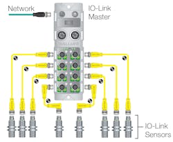
According to the IO-Link Community Consortium, IO-Link is the first standardized I/O (input/output) technology (IEC 61131-9) for communication with industrial sensors and actuators based on the established 3-wire sensor and actuator connection. Though the IO-Link technology has gained wide acceptance and implementation in Europe, its use is not nearly as widespread in the U.S., despite several clear advantages to both OEMs and end users.
To find out more about IO-Link, we connected with Shishir Rege of Balluff, a supplier of industrial sensors, networks, connectors, HMI, and safety products, for a recent episode of the “Automation World Gets Your Questions Answered” podcast. Balluff is well positioned as a knowledgeable resource on IO-Link, as the company has been offering products featuring it since 2009.
In our discussion, Rege noted that one of the main drivers behind the development of IO-Link was the existing signal communications technology—4-20mA analog signals—used by common industrial devices like proximity switches and photoelectric sensors. With the 4-20mA communication method “there are no diagnostics,” said Rege. “We assume everything is working fine until the process comes to a halt and we then discover the problems.”
The other issue that drove the development of IO-Link is the different types of cable and wire sets used by different industrial devices. “Binary devices would use standard two- to three-wire unshielded cables, while analog devices would use two-, three- and even four-wire unshielded cables,” said Rege. “And if you have a complex device, like a pressure transducer with some digital signals, then that requires different types of cables housing anywhere from two to six wires.”
When the devices you use require different set of cables, configuration is tough for OEMs and end users alike. It requires keeping a stock of the different types of cable to guarantee minimal downtime in the case of failures.
Rege said the IO-Link Consortium was formed to address these issues and to develop a unified device level communication method that was both easy to implement and have more built-in diagnostics. The result is IO-Link—a point-to-point communication technology for use at the device level. “It’s like a USB for industrial automation in that it is independent of the control level network, regardless of which protocol you use,” he said. “IO-link is transparent to control networks or fieldbus, as each IO-Link device communicates with a master port residing on a gateway module that takes the device’s data up to the control level.”
IO-Link handles three types of data, Rege explained:
- Process data – on/off signals, discrete sensor data, measurement values, etc.;
- Parameter data – configurations data, engineering units; and
- Event data – data that come from sensors; for example, when a photoelectric sensor indicates that the light intensity on an application has changed.
For OEMs, the advantages of IO-Link include reduced cost of build, faster commissioning times, reduction in network nodes, and more diagnostics. “IO-Link also enables OEMs to integrate more complex devices to make their systems stand out from the crowd and be ready for next generation of machines,” Rege said.
Advantages for end users include all the issues cited for OEMs but, for end users, its downtime and visibility into the plant floor that are most critical, said Rege. “IO-Link addresses downtime by shortening or eliminating it completely due to the high level of diagnostics it provides and how it helps with debugging. For example, if you have a shorted discrete sensor, IO-Link will identify its exact location, meaning that no one will have to hunt for it with multimeters,” he said. “Also with IO-Link sensors, devices are smarter and can provide more alerts and diagnostics so maintenance can be notified of potential problems—such as the pressure being too high, or if there’s not enough current, etc. Maintenance can then plan in a preventative fashion rather than waiting for a problem to occur. IO-Link based systems also feature automatic device replacement configuration—so when you’re replacing a complex device, you can auto-configure it to save a lot of time and not have to save cheat sheets detailing how to configure the devices.”
When it comes to ease of setup—a big concern for end users—Rege noted that there is no programming related to IO-Link set up or maintenance. However, he did clarify that the parameters and process data that come up to the PLC or controller from IO-Link as a stream of data will need to be given meaning for the controller to make sense of it. This can be achieved through basic data mapping, but the most efficient way of doing it is to “use function blocks or add-on instructions that automatically map these data,” he said. “IO-Link device manufacturers often offer this as part of their product to make it easy to integrate.”
Considering the clear benefits to IO-Link, I asked Rege if there were any downsides. He said that, first, it’s important to realize that “IO-Link is for point-to-point communications; it’s not a network. It is not a signal transmission; it is data communication. This means that there will be some time lag from sensor to controller. This lag can be from 2-5ms. My suggestion is this: If your current network operates in the 10-15ms range, then IO-Link is good for that. If it operates at less than 5ms, your use of IO-Link would depend on how critical the update rate is for the application. In my experience 80-90% of data doesn’t have to be updated that fast, so IO-link can be used in the vast majority of applications.”
Leaders relevant to this article:


